How to Build a Cisco SDA Fabric
Let' dig into Cisco SDA technology and how to setup your first fabric from scratch!
DISCLAIMER: In this article I will not dive into Catalyst Center / ISE / WLC integration, I’ll not dive into physical installation and I assume that all the prerequisites defined by Cisco have been accomplished. I want to focus on HOW you discover devices, how you can benefit from LAN Automation tasks to automatically configure switches, how create your SDA Fabric and test some traffic.
Cisco Software Defined Access
Cisco Software-Defined Access (SDA) is a Cisco networking solution that applies software-defined networking (SDN) principles to enterprise campus and branch networks, enabling automated policy enforcement, secure segmentation, and simplified management through Cisco Catalyst Center (formerly DNA Center). SDA uses a fabric architecture that integrates a physical underlay, based on IS-IS routing, with a VXLAN-based overlay to build a scalable, efficient network fabric that eliminates traditional Layer 2 issues like spanning tree. This fabric allows for dynamic network segmentation and improved scalability.
One of the core concepts of SDA is policy-driven automation, where user and device identity-based policies are centrally defined within Catalyst Center and automatically pushed to the network devices, which simplifies onboarding and configuration tasks. SDA also focuses on zero-trust security by implementing micro-segmentation using Scalable Group Tags (SGTs) and macro-segmentation through Virtual Networks (VNs), ensuring secure and granular access control.
The SDA architecture is built around key components, including the Catalyst Center for centralized management and assurance, the Identity Services Engine (ISE) for policy enforcement and authentication, and specialized fabric edge and border nodes that handle endpoint connectivity and interaction with external networks.
Here are the four key technologies involved:
- Overlay control plane: Messaging and communication protocol between infrastructure devices in the fabric –> LISP
- Data plane: Encapsulation method used for the data packets –> VXLAN
- Policy plane: Used for security and segmentation –> TrustSec
- Management plane: Orchestration, assurance, visibility, and management –> Catalyst Center (formerly DNA Center)
Physical Topology

As you can see from the diagram, we have:
- 2x Control and Border Nodes. In my lab the role of Control and the role of (External) Border have been assigned to the same device.
- 3x Edge nodes where endpoints and APs are connected. Each edge node has 1 link to C/B #1 and 1 link to C/B #2.
- 1x Fusion Switch wher C/B Nodes are interconnected and established BGP peerings. Behind this switch we have internet and datacenter connections.
- 1x Catalyst Center
- 1x Core Switch external to the fabric. This switch will establish BGP peering with the SDA Fabric in order to announce default router (both underlay and overlay).
Nothing special 😉
Please consider that the Edge nodes are wiped like just pulled out the boxes, never powered on. I’ll access them thought a remote console connection (thank you Opengear
) and see you how the LAN Automation take care of the entire switch configuration without any human interaction.
Logical Topology
After the physical part, that usually it’s the annoying one, let’s dive into logical infrastructure
IP Pool
In SDA, an IP Address Pool is a subnet that Catalyst Center uses as the source for host addressing, underlay addressing, or infrastructure functions, instead of configuring subnets manually on switches. Pools are defined globally and then reserved/assigned to sites and VNs, where they become host pools used for wired/wireless endpoints or infrastructure pools used for underlay/LAN automation. For our lab I’ll define the following IP Pools:
- IP_Global (type “generic) - 172.16.0.0/12 –> must be created at the Global level and it will be associated to all the other Site Specific IP Pools
- LAN Automation (type “LAN”) - 172.25.192.0/24 –> Catalyst Center will use this IP Pool to configure all the /31 between C/B and Edge nodes.
- IP_CORP (type “generic”)- 172.25.193.32/27
- IP_GUEST (type “generic”) - 172.25.193.96/27
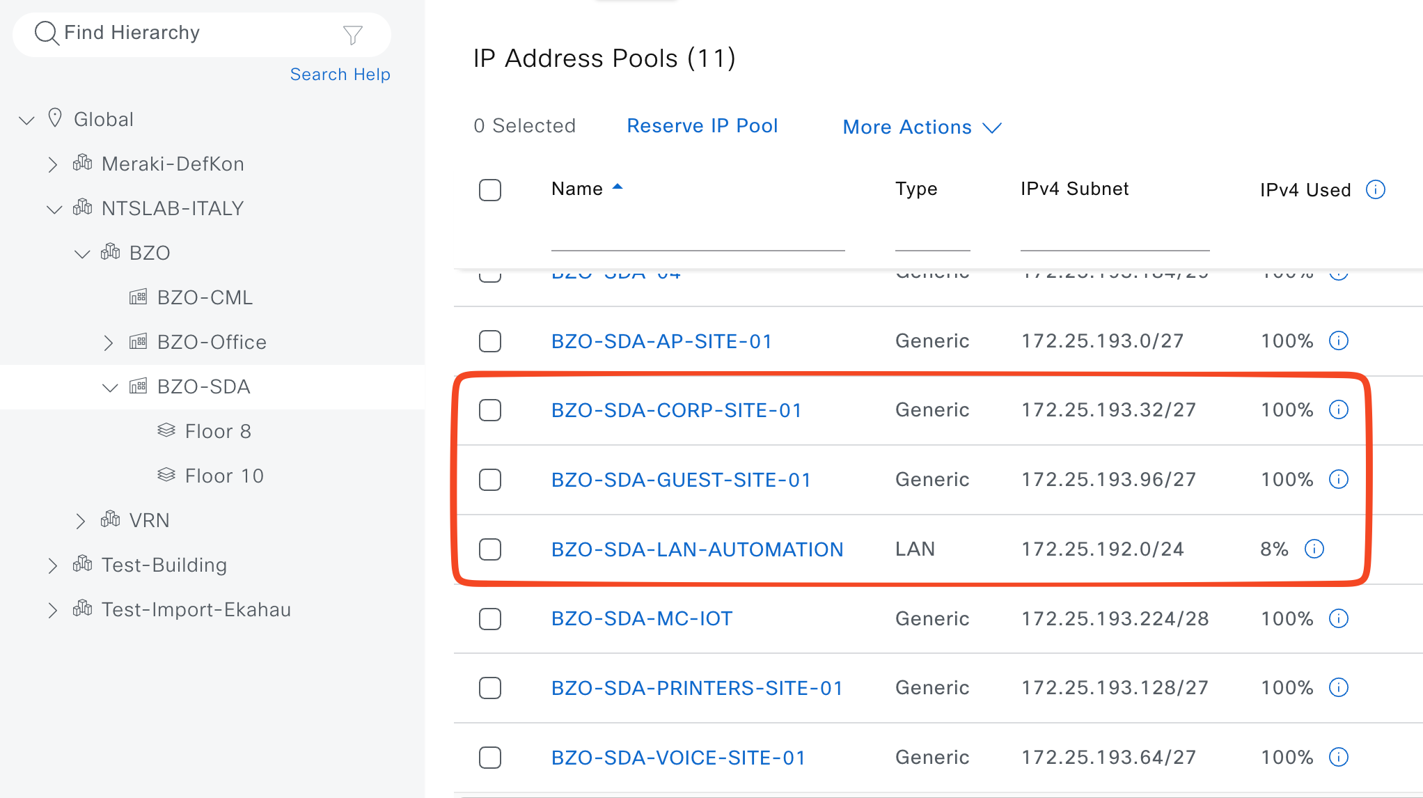
IP Pools are defined here: Design > Network Settings > IP Address Pools
Usually a Global IP Pools (a big one, like /8, /12, /16 or something like that) is defined and then “n” Site Specific IP Pools (like we’ve done in te screenshot below). The Site Specific IP Pools must be contained into the Global IP Pool
Virtual Networks
A Virtual Network (VN) in SDA is effectively a Layer 3 virtual network/VRF that provides macro‑segmentation, allowing separate routing and policy domains to coexist over the same physical fabric. For our lab I’ll define the following VNs:
- CORP
- GUEST
VNs will be configured when the SDA Fabric will be ready.
Anycast Gateway
An Anycast Gateway in SDA is a default gateway interface (SVI) whose IP and MAC address are identically instantiated on all fabric edge nodes for a given subnet, so endpoints can keep the same default gateway regardless of which edge they attach to. This distributed gateway behavior extends the subnet across the fabric and enables optimal local routing, seamless mobility, and efficient handling of traffic path. For our lab I’ll define the following Anycast Gateways:
- 1.1.1.1
- Associated VN: CORP
- Associated IP Pools: IP_CORP
- Wireless: Yes
- 1.1.1.2
- Associated VN: GUEST
- Associated IP Pools: IP_GUEST
- Wireless: Yes
Anycast Gateways will be configured when the SDA Fabric will be ready.
L3 Handoff
An interesting topic when talking about Cisco SDA is how we interconnect SDA fabric to the external world. How endpoints can talk with public cloud apps? How your customer can access the internet?
Well, some devices are involved in this funny part:
- Border Nodes (rememeber that in our lab we give to the Border nodes also the Control role)
- Fusion Nodes: this devices are not directly managed by Catalyst Center and they are not part of the SDA fabric. Usually they are manually configured, BUT we can add them to Catalyst Center Inventory and enpower its features like SNOW, CLI Templated push and much more.
L3 Handoff consist of configuring 1 Point-to-Point interface between Border and Fusion nodes per each Virtual Networks. In our example, I’ll configure two point-to-point interfaces between C/B #1 and Fusion and two from C/B #2 and Fusion.
On top of this logical links we’ll establish a eBGP peering. How we configure eBGP peering?
- From Fusion to Border –> Announce only default route 0.0.0.0/0 (use prefix-list + route-map to accomplish this task, it will allow you to manipulate traffic if needed)
- From Border to Fusion –> Catalyst Center automatically announce the “aggregate summary-only” of each Anycast Gateway associated to the related Virtual Network, you don’t have to take care of that.
The logical interconnection is done via SVI from C/B Nodes point of view. Catalyst Center will automatically configure the physical link as a trunk port (trunk all) where the VLAN traffic will go.
From Fusion point of view, it’s up to you to configure SVI or routed sub-if (I prefer this solution)
❗ TIP(S)❗
- Manually configure the underlay (GRT) temporary point-to-point in both C/B Nodes and also manually configure just the first temporary BGP neighbor to Fusion switch. Why? It allows us to reach Loopback0 of each C/B Nodes from Catalyst Center and, later, we’ll configure the permanent point-to-point connection between C/B Nodes and Fusion throught Catalyst Center. Thanks to this small task we’ll be sure that all the BGP configuration will be managed by Catalyst Center witouth any human errors.
- If you want to aggregate the entire VN announcement, you can not do it automatically via Catalyst Center but you have to configure CLI Template and push them to C/B Nodes. Example:
CORP VN (pre-defined 172.16.0.0/16) has 12 Anycast GW (172.16.1.0/24, 172.16.2.0/24 … 172.16.12.0/24), by default Catalyst center will announce the Anycast Gateway network via BGP, so only the /24 networks. If you want to optimize the BGP announcements, please consider to implemente ad-hoc CLI Template to accomplish this task. Remember, any manual change directly to switch CLI is not recommended.